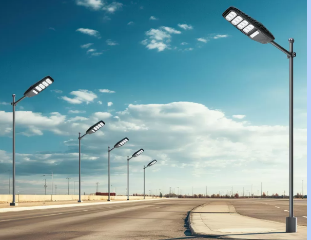
When purchasing solar street lights, a photometric report will indicate whether the proposed luminaire can adequately illuminate a road, pathway, or plaza as required by the project. A high-quality photometric report translates the manufacturer’s optical claims into actual performance, including horizontal lux, vertical lux (a measure of visibility), surface uniformity, glare risk, and patterns for determining pole spacing. Data-driven buyers consider photometrics a core technical filter in their procurement process, as it enables an objective comparison of competing offers and a reliable sizing of photovoltaic/battery systems based on energy consumption derived from light output curves.
Photometric Basics of Solar Street Lights
To evaluate photometric reports for solar street lights, it is essential first to understand basic photometric terminology, as vendors often package these terms in standard documentation. Lumens measure the total light output of a luminaire. Candela (cd) describes angular intensity—the number of lumens per steradian emitted by a luminaire in a given direction. Lux (lx) represents surface illuminance: lumens per square meter. Photometric documentation maps the distribution of candela values at different angles, allowing simulation software to convert this distribution into predicted lux on a given surface.
Photometric data is typically provided in standard formats, such as IES (LM-63) or EULUMDAT (LDT). These formats encode the angular candela distribution and metadata (luminaire height, nominal lumens, tilt). Photometric reports display isolux plots, polar candela plots, and summary tables of predicted average illuminance, minimum illuminance, and uniformity ratios for given mounting heights and spacing geometries.
Finally, pay attention to the rotational symmetry of the reported light intensity distribution and whether the file was collected for the provided luminaire model and optical configuration. Slight variations can cause distribution shifts that significantly alter spacing and uniformity. Always request photometric files that match the actual part number you receive.
How to Interpret a Photometric Report?
A practical photometric assessment begins by loading the supplier’s IES or LDT file into a lighting simulation tool. These tools convert the candela distribution into predicted lux values for the target surface based on the mast height and spacing. Key visual outputs to review include the isolux plots, longitudinal and transverse illuminance distribution plots, and polar candela plots.
When reviewing isolux diagrams, pay attention to the following: the maximum illuminance at the pole location (safe but not excessively glaring), the average illuminance on both sides of the road, and the minimum illuminance at the darkest point between poles. Since results vary depending on the plane, be clear about the target plane you are using.
Photometry derives the spacing-to-height (S/H) ratio as a helpful shorthand, expressing the recommended spacing as a multiple of the mounting height. Typical street lighting systems produce S/H values of approximately 3 to 6, depending on the distribution. For example, a Type III front-projection lighting system installed at a height of 6-8 meters on a residential road produces an S/H value of approximately 3.5-4, but this requires verification through actual IES simulations.
Key Photometric Metrics for Solar Street Lights
When evaluating photometric reports for the solar street light, prioritize key performance indicators related to safety and comfort: average illuminance, minimum illuminance, uniformity, glare index, and color quality (CCT and CRI). These metrics determine the user experience and compliance with local lighting standards.
Average illuminance is the average lux over a defined plane. Designers set targets based on the application: typical residential streets typically target 5–20 lux for driveways, 20–40 lux for catchment areas, and 30–75 lux for arterials. Regarding minimum illuminance and uniformity, uniformity is more important than peak lux, as dark spots can reduce perceived safety. As a general rule, Uo should be ≥ 0.3 for residential streets and ≥ 0.4 for arterials and intersections; however, this should be adjusted according to local standards. Polarization of illumination and stray light is also important to ensure that optical components minimize glare (U1-U3 categories) to limit light trespass and energy waste, and to verify the luminaire’s cutoff angle against dark sky targets.
Photometry, Energy Use, and System Sizing: Dimming Curves and Duty Cycles
The photometric output directly drives the energy consumption model for solar street lights, as the output illuminance determines the required LED power, which in turn determines the energy consumption. Therefore, when purchasing, use the expected daily operating hours and dimming strategy to translate photometric results into a realistic energy budget.
Simulation software reports the lux output per watt at a given mounting altitude. Use this lumen/watt relationship to calculate nighttime energy consumption at the target illumination level. For example, a luminaire with an average output of 20 lux at an 8-meter altitude might require a nominal LED power of X watts. The system maps this power to daily power consumption and, after accounting for derating and runtime hours, to the required PV power and battery capacity.
Dimming can significantly reduce the size of photovoltaic (PV) and battery systems. For example, a typical dusk-to-dawn configuration might operate at 100% brightness for the first three hours after dusk to account for high pedestrian activity. It would then dim to 50% brightness during periods of low nighttime activity, and then increase brightness again during late-night periods when activity is high. Lumen rolloff (L70) and seasonal solar variations should also be taken into account.
Photometric Verification, Acceptance Testing, and Purchase Terms
The final, and most crucial, step is to verify that the installed solar street lights meet photometric expectations. Do not accept a system without contractually specified photometric acceptance criteria, laboratory test references, and on-site commissioning tests.
Require the manufacturer to provide the following documents: LM-79 photometric test reports, LM-80 lumen maintenance data for LED modules, and IES or LDT files used for simulation. Opt for third-party laboratory certification whenever possible. The contract should include acceptance testing, which involves measuring horizontal and vertical illuminance on a sample pole. This requires the measured Eavg to be within ±15% of the simulated value and uniformity to be no less than 0.05 of the absolute value of the simulated Uo. For the dimming operation, measurements should be taken at each programmed dimming level. Also, verify actual delivery hours, dimming behavior, wireless telemetry, and failure rates over an agreed-upon burn-in period (e.g., 90 days). For remote or high-security locations, thermal imaging and photopic/mid-sight inspections should be included to confirm light distribution and glare performance.
Ultimately,
Evaluating photometric reports is the most effective way to ensure your solar street lights provide the right amount of light in the correct location at the optimal energy cost. To summarize, adhere to IES/LDT files and LM-79/LM-80 standards, load the files into simulation tools, and, based on the exact pole height and road geometry, evaluate the average lux and uniformity for your use case. Check for glare and bug levels, and translate photometric results into an energy budget, including a dimming strategy. Then, request a site acceptance test with clearly defined tolerances, and establish contractual remedial measures if the results deviate.